
Camera
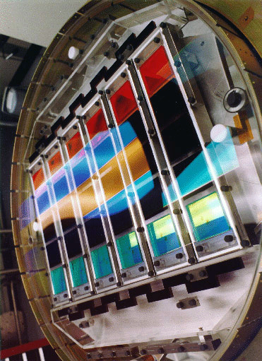
The imaging camera collects photometric imaging data using an array of 30 SITe/Tektronix 2048 by 2048 pixel CCDs arranged in six columns of five CCDs each, aligned with the pixel columns of the CCDs themselves. SDSS r, i, u, z, and g filters cover the respective rows of the array, in that order. The survey operates the instrument in a drift scan mode: the camera slowly reads the CCDs as the data is being collected, while the telescope moves along great circles on the sky so that images of objects move along the columns of the CCDs at the same rate the CCDs are being read. As an image of an object moves along the column of the CCDs, a CCD in each row collects data on that object. Therefore, the camera produces five images of a given object, all from the same column of CCDs, one from each CCD in that column. It takes an object 54 seconds to move from the beginning of a CCD to the end, so the effective exposure time in each filter is 54 seconds. Because there is some space between the rows of CCDs it takes an image 71.7 seconds to move from the beginning of one row to the next. Each row corresponds to a different filter, so each object has one image in each filter, taken at 71.7 second intervals.
An additional 24 CCDs placed before and after the photometric CCDs collect astrometric data. Neutral density filters cover these CCDs, and allow collection of data on bright reference stars without saturation. In practice, the UCAC2 network of calibration standards extends to magnitudes fainter than the saturation limit of the main camera. so the data from these astrometric chips is not needed for calibration.
Because there is space between the columns of CCDs, two passes along a great circle are required to obtain a solid area. The second pass is offset from the first such that the area that fell between columns in the first pass is images in the center of the columns in the second pass.
Filters
Filter Wavelengths
SDSS-III used the same filter system as the original SDSS. These are the central wavelengths of the six filters.
- u
- 3551Å
- g
- 4686Å
- r
- 6166Å
- i
- 7480Å
- z
- 8932Å
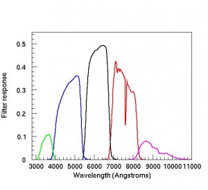
Tables of camera sensitivity through each filter, as determined by Jim Gunn in June 2001, are available as a FITS file.
Note that Doi et al. 2010 have published more recent estimates of the filter curves using more data and over a longer time baseline. They found that the u band in particular has changed over time and appears to differ now from the curve estimated in the 2001 filter curves distributed above.
The response curves on the right correspond to the second column in the tables above and show the throughput defining the survey's photometric system, which includes extinction through an airmass of 1.3 at Apache Point Observatory. Note that these are not "complete" filter curves, as they do not include the full system response from atmosphere to detector.
The photometric flux calibration web page is essential reading for those wishing to understand the SDSS photometric system, and includes a long description of transformations between the SDSS (ugriz) and Kron-Cousins (UBVRcIc) photometry.
Main Parameter Summary
- Photometric CCDs
- 30 2048 × 2048 SITe/Tektronix 49.2 mm square CCDs,
arranged in 6 columns parallel to the scan direction and 5 rows perpendicular to the scan direction - CCD read noise
- < 5e- pixel-1 (overall system is sky limited)
- image frame size
- 2048 × 1361 pixels (13.51 × 8.98 arcminutes)
- Image column separation
- 25.17 arcminutes
- Detector separation along column
- 17.98 arcminutes
- Focal-plane image scale
- 3.616 mm arcmin-1
- Detector image scale
- 3.636 mm arcmin-1
- Pixel size and scale
- 24 μm; 0.396 arcseconds pixel-1
- Filters
- r i u z g scanned in that order, 71.7 seconds apart
- Integration time
- 54 s
- Operating mode
- drift scan
- Field distortion
- <0.1 arcseconds over the entire field
- Field size
- 2°.5
- Flux calibration
- Standard-star fields at 15° intervals along scans, tied to BD + 17° 4708, atmospheric extinction determined by the PT
- Astrometric CCDs
- 22, 0.25 × 2 inches, above and below CCD columns; r filter plus 3 mag neutral density filter, 10.5 second integration time